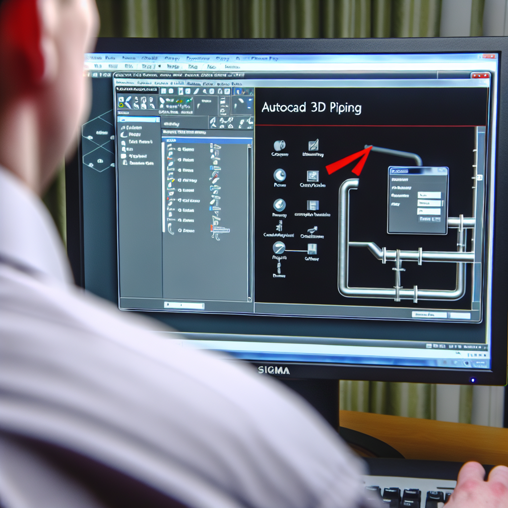
Automating and streamlining complex piping designs in plant projects is crucial for efficiency and accuracy. AutoCAD Plant 3D offers powerful tools specifically for piping modeling, enabling engineers to create detailed, precise, and manageable plant layouts. In this article, we explore a demo of AutoCAD Plant 3D piping, its features, and best practices to optimize your workflow.
Understanding AutoCAD Plant 3D Piping Tools and Features
AutoCAD Plant 3D provides a comprehensive suite of tools tailored for piping design, making it a preferred choice for engineers in industries like oil and gas, chemical processing, and utilities. These features include intelligent piping components, automated routing, and clash detection. The demo showcases how users can leverage these tools to develop detailed 3D piping models efficiently.
One of the core features highlighted in the demo is the use of predefined pipe specs and fittings, which facilitate standardized and consistent designs, reducing errors. The software’s intelligent components are context-aware, allowing for modifications and updates to propagate throughout the model, maintaining integrity across the entire project.
Another vital aspect is the dynamic routing capability. The demo demonstrates how to create complex pipe runs with minimal manual adjustments, thanks to AutoCAD Plant 3D’s automatic elbow and fitting placement in accordance with specified parameters. This significantly speeds up the design process and improves accuracy.
Furthermore, clash detection and interference checks are integrated into the workflow, enabling early identification of potential problems that could cause costly delays later in construction. These features empower engineers to design safer, compliant, and more efficient piping systems from the outset.
Optimizing Your Pipe Design Workflow in AutoCAD Plant 3D
Efficiency in piping design hinges on leveraging the full capabilities of AutoCAD Plant 3D effectively. The demo illustrates the importance of setting up project standards and templates, which streamline the creation of consistent pipe specifications and components. Using these standards ensures that all team members work with uniform data, reducing miscommunication and rework.
It’s also crucial to utilize the software’s catalog and parts database, which provides an extensive library of fittings, valves, and other components. Customizing catalogs to match specific project requirements can optimize the selection process and ensure that all parts conform to industry standards and project specifications.
Moreover, integrating AutoCAD Plant 3D with other project data, such as P&ID diagrams and isometric drawings, helps maintain data consistency and improves coordination among disciplines. The demo underscores how importing and referencing external files can facilitate seamless collaboration, ultimately leading to faster project completion and minimized errors.
Finally, practicing iterative design and validation within the software allows for continuous optimization. By utilizing clash detections, stress analysis, and real-time modifications, engineers can refine their piping layouts early in the process, saving time and resources during construction.
Conclusion
AutoCAD Plant 3D piping demos highlight its robust capabilities for creating accurate, efficient, and standardized plant designs. Understanding key tools—from intelligent components to clash detection—enables engineers to streamline their workflows and reduce costly errors. Mastery of these features leads to safer, compliant, and more productive piping projects. Embracing AutoCAD Plant 3D ultimately benefits project timelines, costs, and quality.
